Trigger switch Mods for Lightguns
light guns, with extremely responsive and pleasantly feeling arcade
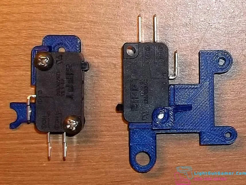
microswitches. I include 50-gram force ‘light touch’ switches with all
of my kits. They allow for consistent and quick modification, and are
all reversible in the event you wish to return back to stock
configuration of your guns. Some kits such as the Guncon 2 can be even
used to repair broken trigger pieces as they augment the original
plastic.*
If you are interested in these kits then you can get more information from the creator on Twitter at @MagicTrashman
This video gives a really good overview of these switches:
Gcon1
The PS1 Guncon switch kit has been designed to be used with standard microswitches.
Lift the original Guncon trigger button out of its holding track in order to press your new bracket into place. While it is a snug fit, you may want to secure it with a dot or two of hot glue to keep it from rocking out of alignment.
Remove the original button board entirely and wire the normally open and common tabs in its place.
You may want to lightly bend these switch tabs to ensure they don’t rub and cut into the controller cord after you slip it back into place.
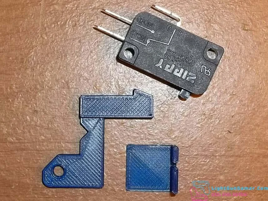
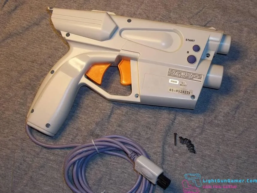
Gcon2
This kit installs a microswitch inside of the Playstation 2 Guncon 2, for improved tactility and more accurate trigger pulls. It also works as a fix for triggers with broken switch actuators (which is a common issue, because the original plastic is so thin). This kit was primarily designed for the ‘Made in Japan’ NPC-106 model which has black screws. If you have the ‘Made in China’ version with silver screws, the kit will work, but please review these additional instructions to fit the trigger piece, as it is slightly different: https://imgur.com/a/vWb9o8n
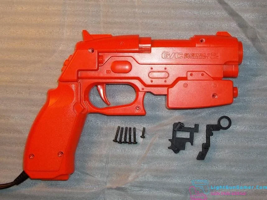
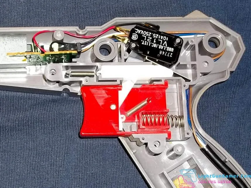
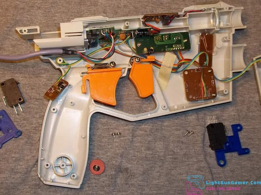
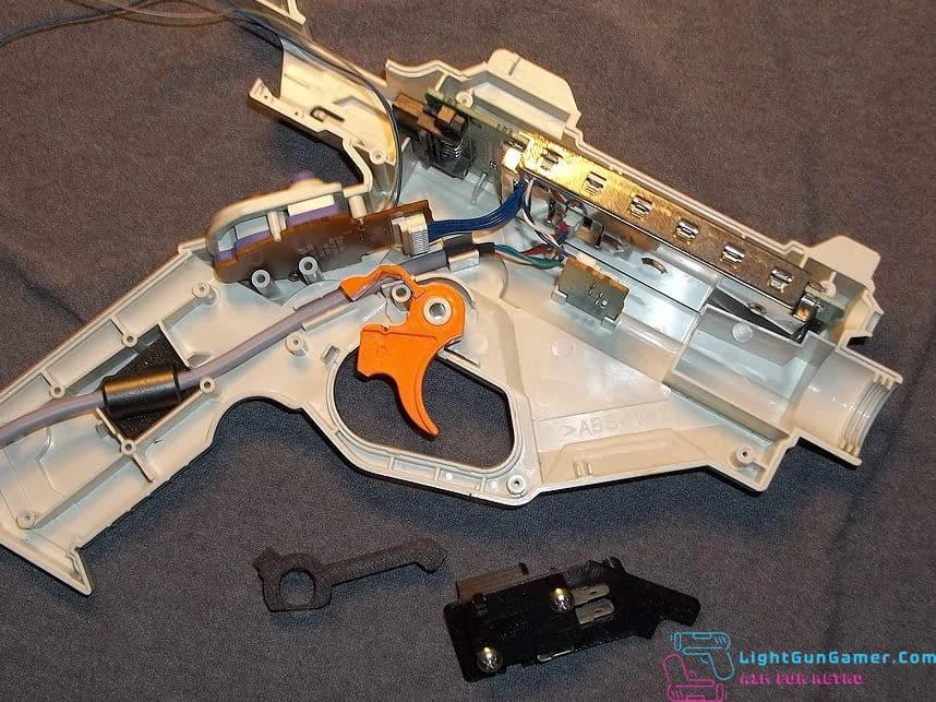
Be aware that this mod is a little more complicated than previous light gun switch kits since the interior of the Guncon 2 is very crowded. Unscrew the six screws holding the shell together and set the upper half aside.
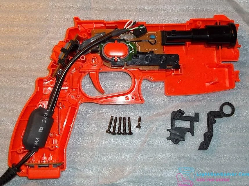
Take a note of the general layout and unplug the cord from the PCB above the B button, or simply move it aside. You’ll also want to move the magazine bottom button out of the way.
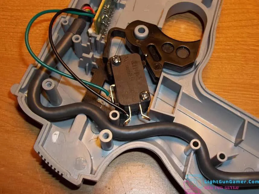
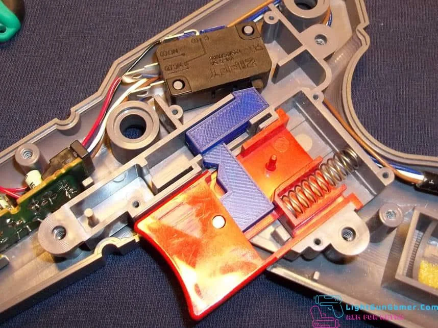
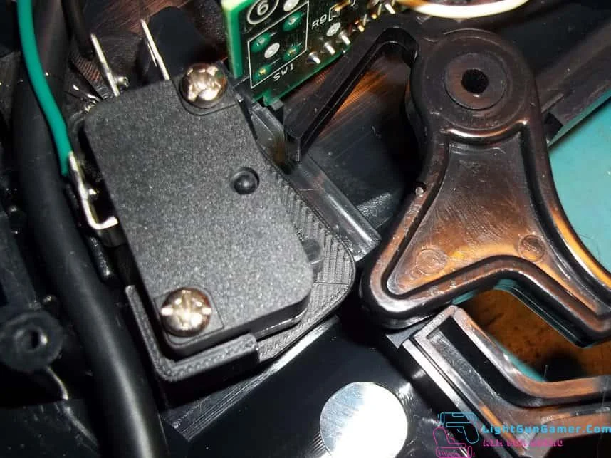
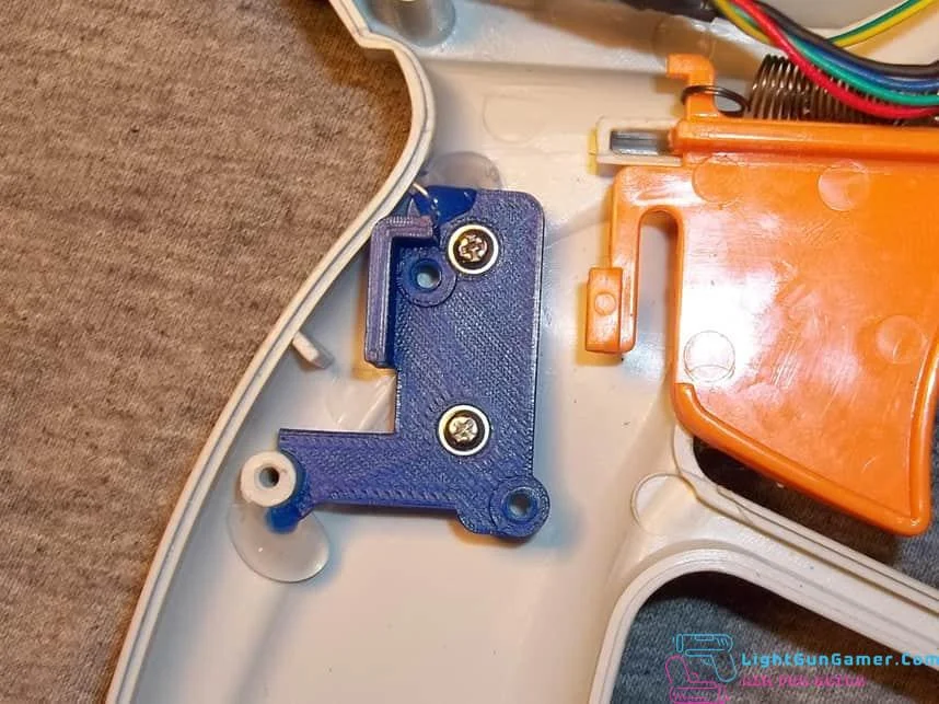
Place the switch bracket as pictured, it’s designed to be a snug fit, but there appears to be enough variation in ABS injection molding that you should secure it with a couple dots of hot glue so that it never shifts out of alignment.
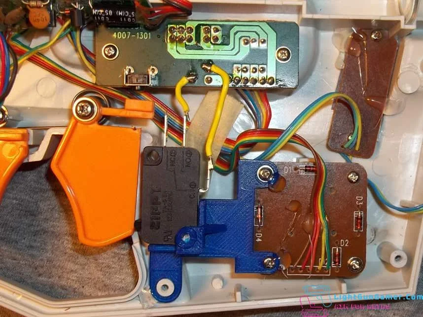
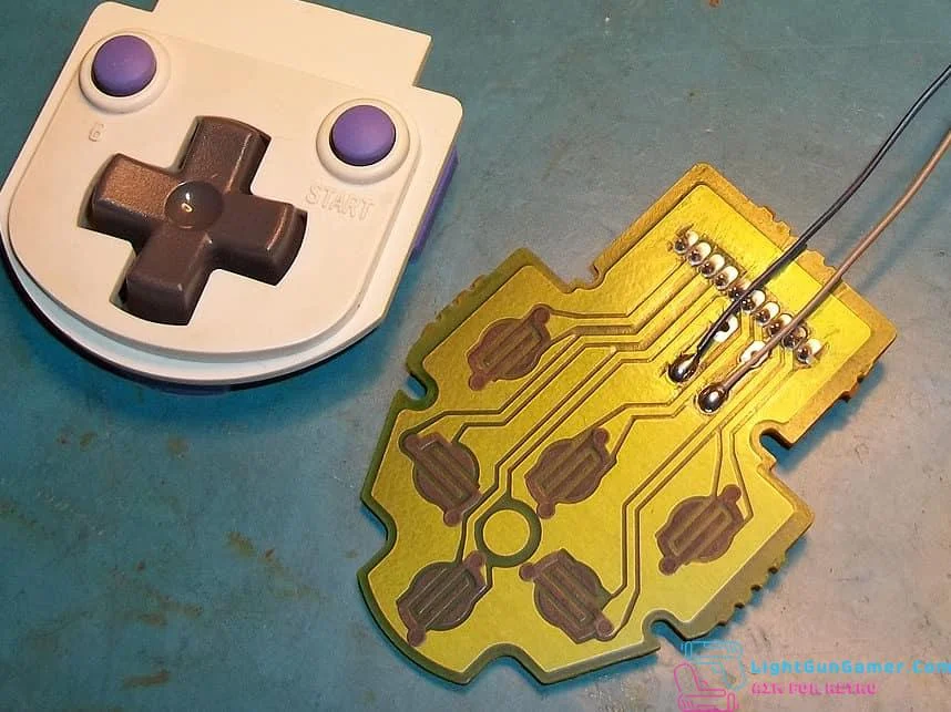
Remove the trigger/d-pad PCB and desolder or clip out the original trigger button, then solder wires to the points shown.
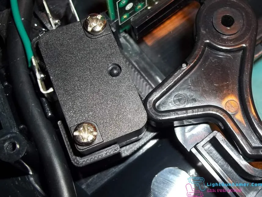
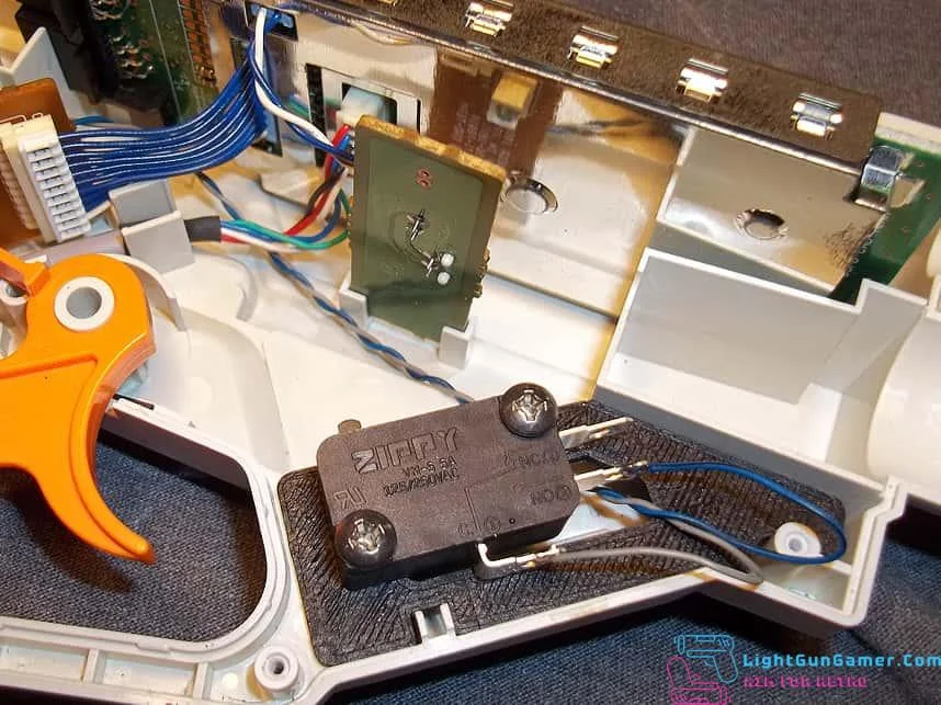
Connect the wires to the common and normally-open tabs of the switch and screw the switch into place if you haven’t already. Note that you may have to bend the normally-open tab as shown so that it clears the interior plastic of the Guncon shell. You may also want to extend the wires of the magazine button below as it will make things much easier for reassembly when the time comes.
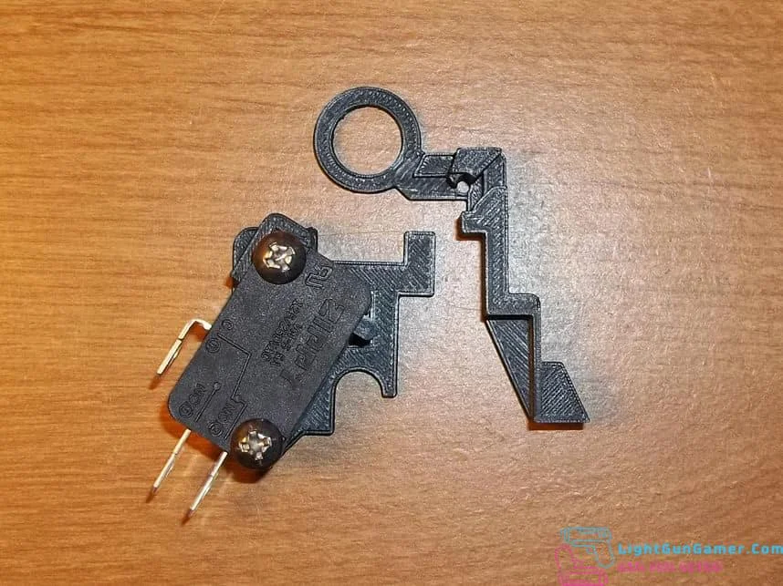
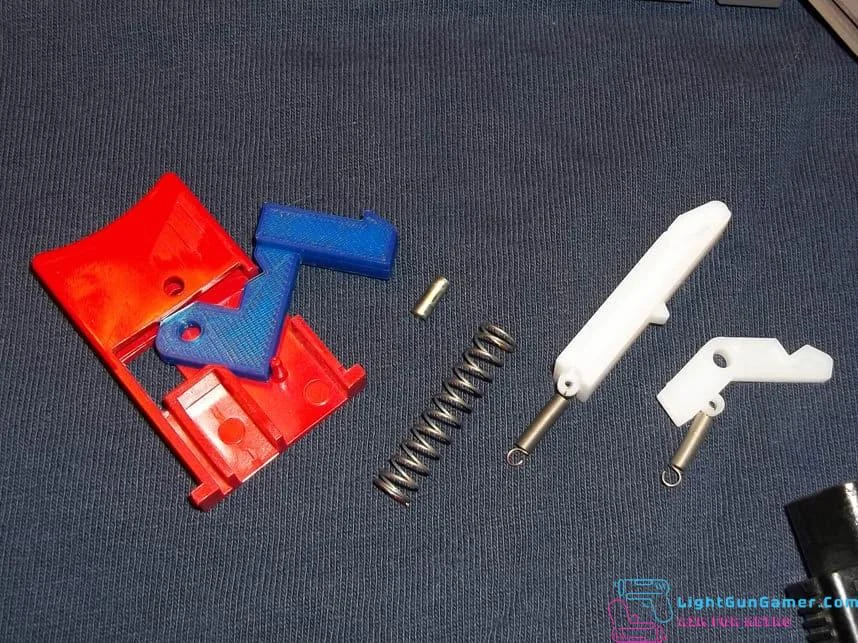
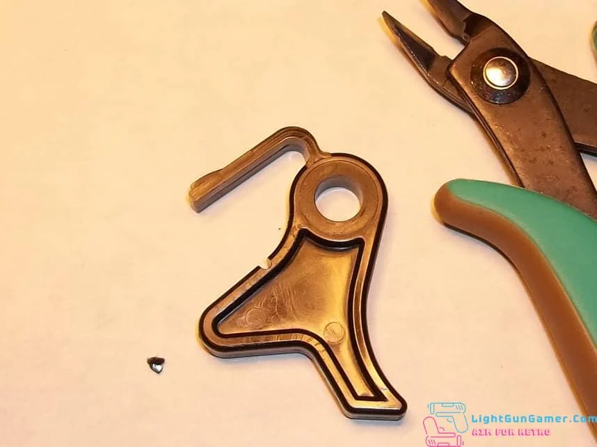
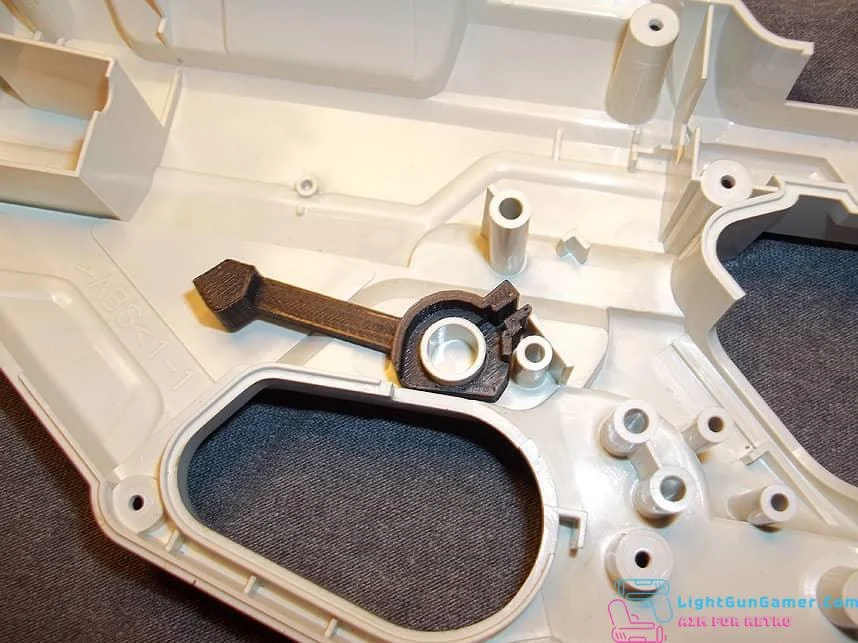
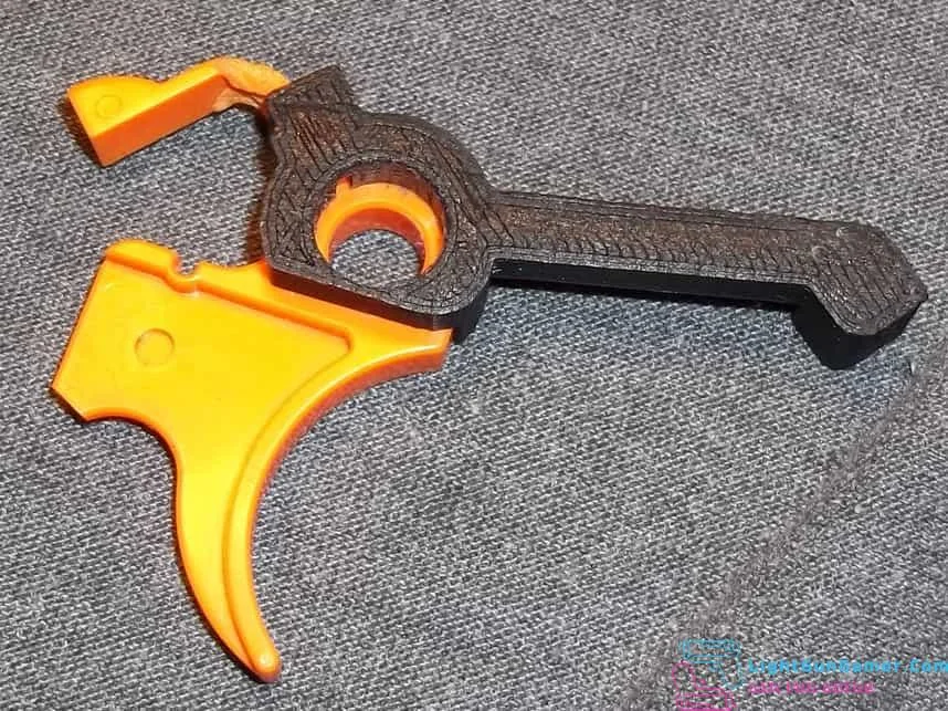
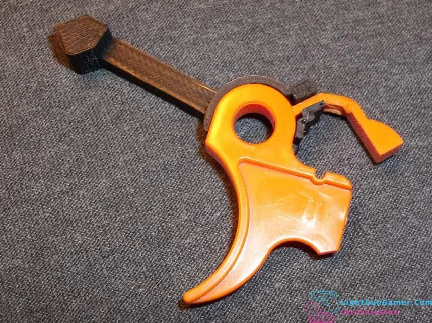
The second half of the switch kit mates with the original trigger to extend its reach- be very careful applying this, you might have to file, sand or shave a little inside the hole that slips over the circular peg of the trigger. Designed to be a snug fit, but excessive force shouldn’t be necessary.
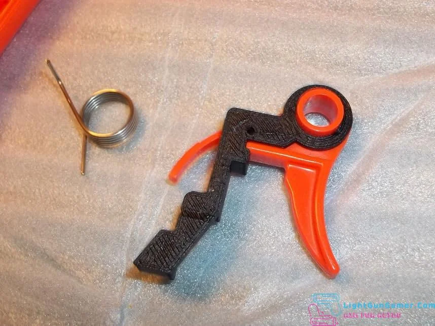
Mated pieces as shown above.
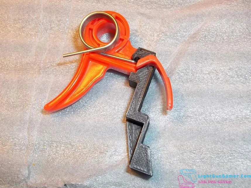
The spring slips into the back of the trigger as shown, be sure that it pokes through the tiny hole and extends past the new plastic or your trigger won’t seat properly.
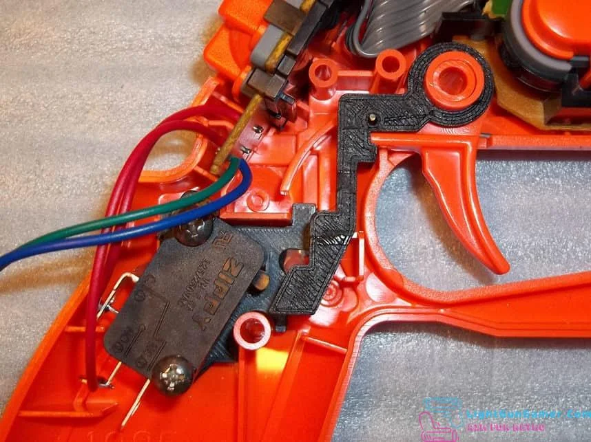
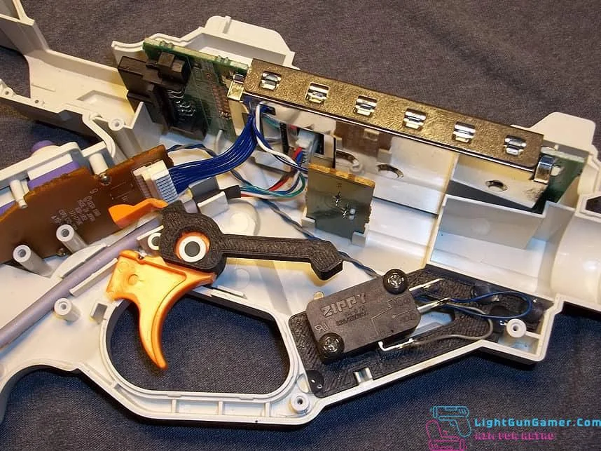
Place the trigger back into position as shown, be sure to test the action to verify that it will activate the switch.
It’s time to put the controller cord back in. Bend the normally-closed tab of the switch like this to make as much room as possible without touching the neighboring tab.
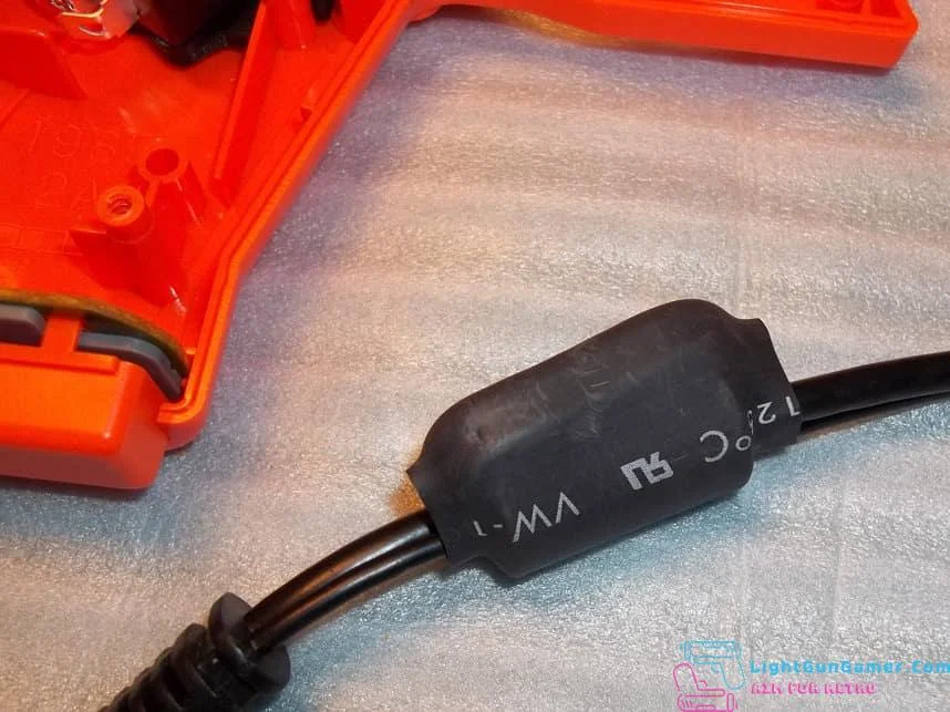
There is a ferrite bead on the controller cord that can prove troublesome when closing everything back up, you’ll want to cut away the heatshrink covering it, but be careful not to cut into the insulation of the wires. Don’t forget to plug it back into the PCB.
With the heatshrink removed, you can adjust the loop around the ferrite bead to shift it a little further down if necessary, and also move the cable around until you’re able to close the plastic shells together. Alternatively, you could take a hammer and smash the ferrite bead to remove it from the cord, but I personally prefer modifying things in such a way that I can return them ‘back to stock’ if I ever wanted to.
Screw the shell back together and test the trigger action to verify that it’s light and springy. If it’s not, you’ll have to open it back up and rearrange something. Be very cautious that you don’t pinch any cords or wires as you close things up. Currently I supply all kits with 50 gram force switches, but you can change that to the switch of your personal preference if you have any.
GCon3
This kit installs a microswitch inside of the Playstation 3 Guncon 3, for improved tactility and more accurate trigger pulls. Since the PS3 gun is even more condensed inside than the PS2 version, please take care with the modification! The trigger piece by necessity has a thin component that could be snapped off if you mishandle it!
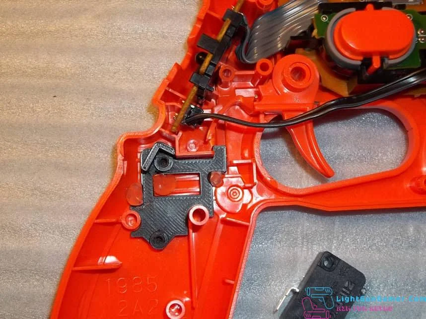
On opening up the Guncon 3 you’ll note that the circuitry is on the left half while the trigger (and where the switch will go) is in the right half. Remember that the two shortest screws go in the trigger guard area, for future reference when you close everything back up.
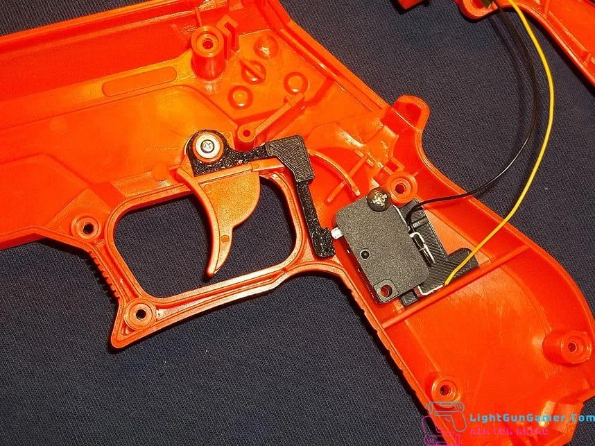
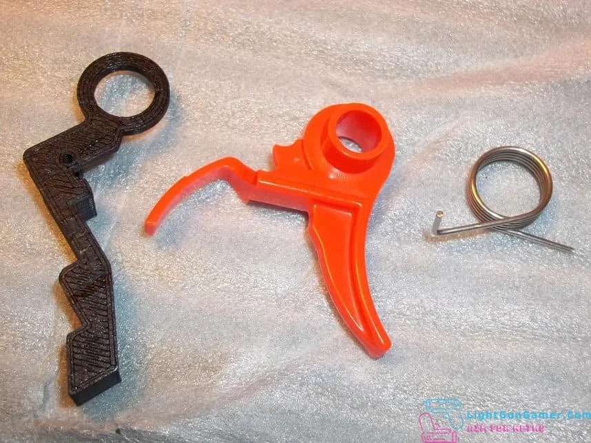
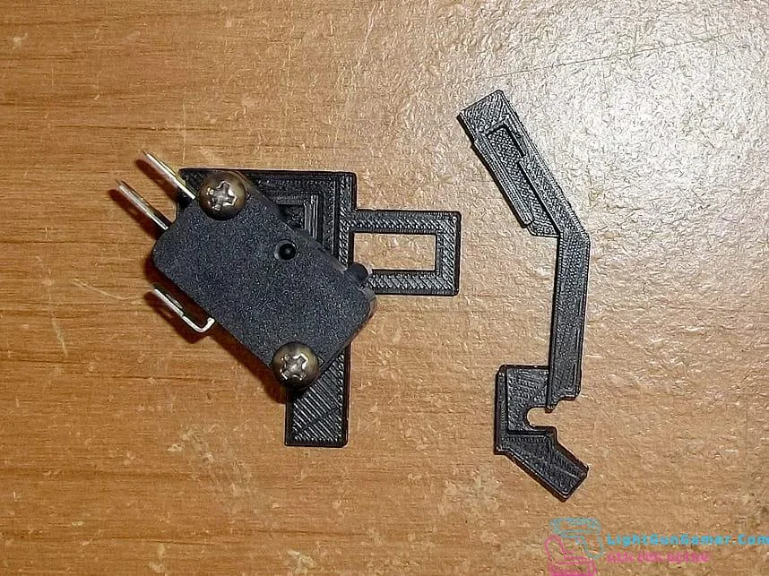
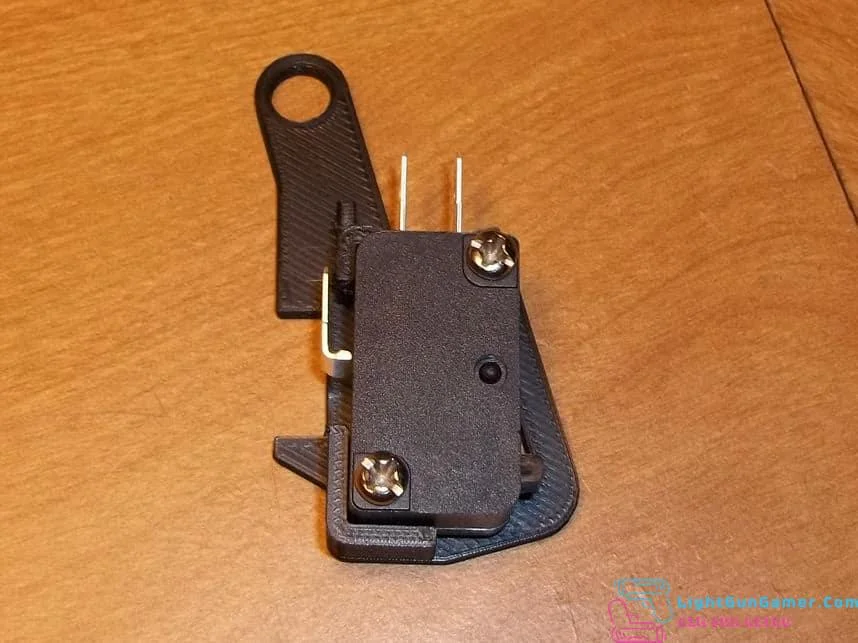
Before pressing the switch and bracket into place, you’ll want to bend the bottom tabs at right angles. You may even want to bend-break the unused normally closed tab as shown above. Connect wires to the normally open and common tabs, then press-fit both the trigger piece and bracket into place. If you find the trigger piece doesn’t slide into place easily, you may have to use a file to sand the inside of the hole that slides over the trigger plastic to get it started. Also note that the trigger spring’s shaft needs to slip through a small hole so everything sits flush.
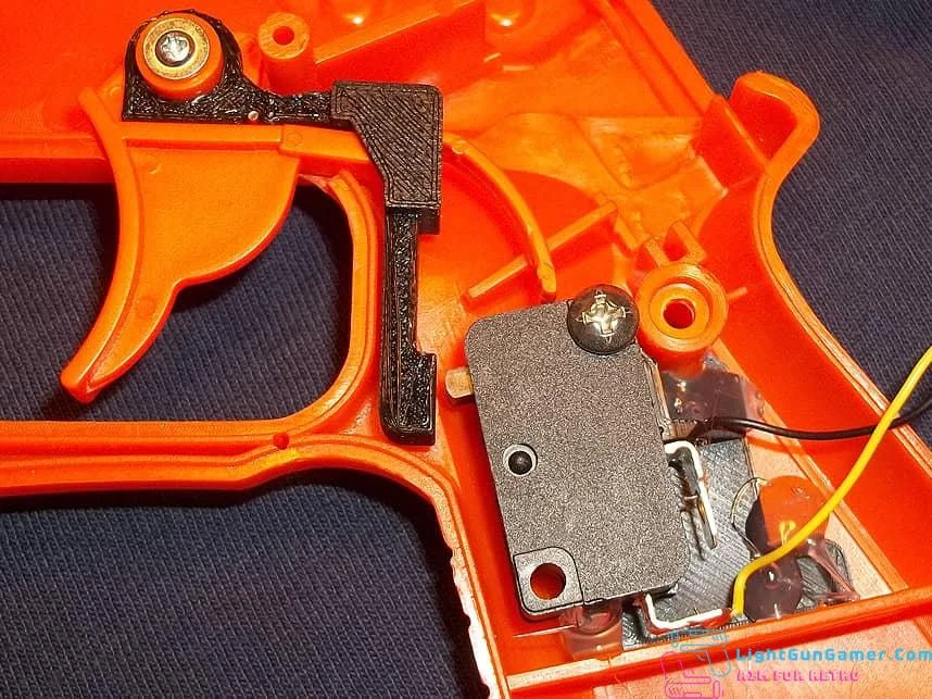
It wouldn’t be a bad idea to apply a few dots of hot glue as shown to keep the switch bracket from swinging out of position. Be sure to test the trigger action to determine that everything’s aligned properly.
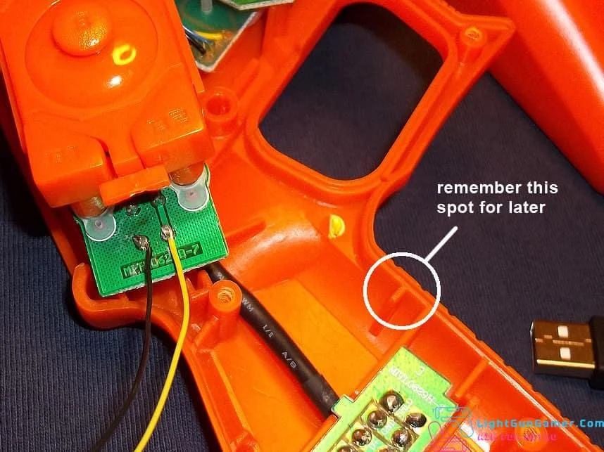
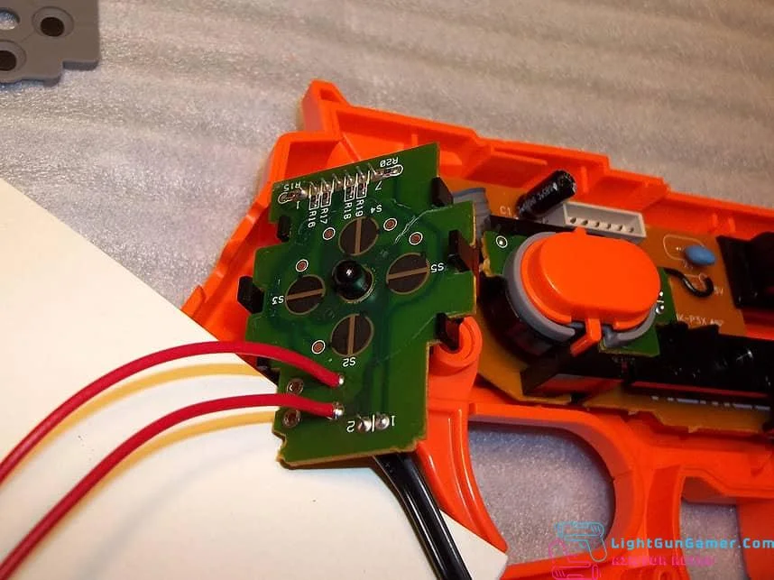
Solder the other end of the wires to the two points as shown on the control board- you shouldn’t have to physically remove the original switch but you can if you want to at this point. Be sure to note the circled spot in the inside of the gun grip for later reference.
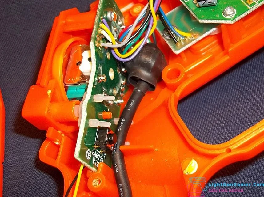
When replacing the control board, you’ll probably want to make sure the main cable is routed as shown to keep it out of the way. And when you go to close everything back up, be extra careful to keep any wiring from getting pinched by the shell halves coming together.
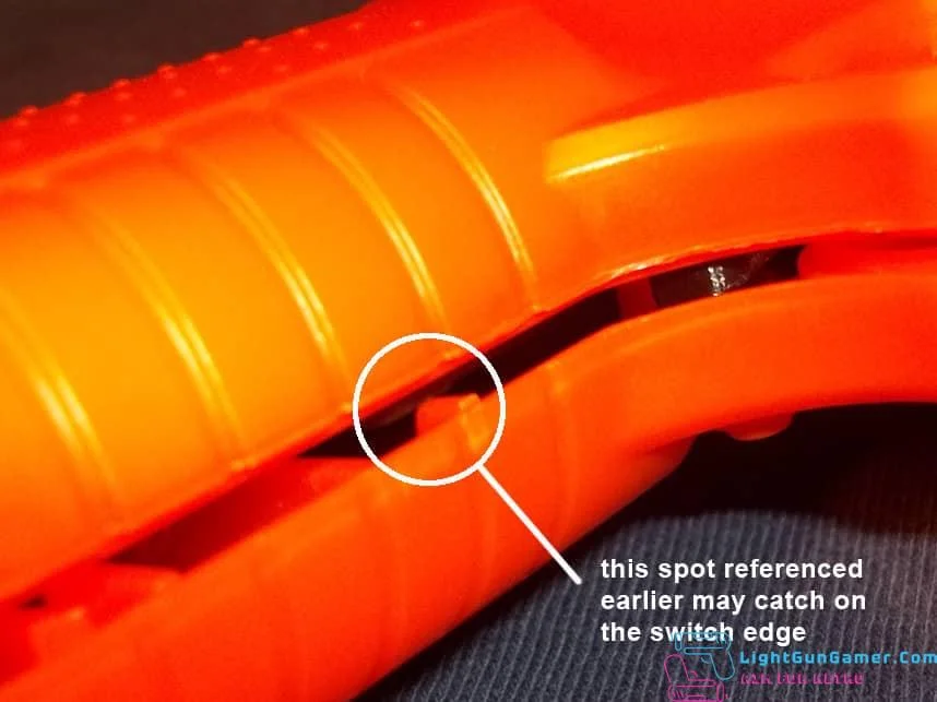
When you’re about to close everything back up, you may encounter a little snag. The edge of the microswitch could catch on the plastic piece pointed out to you earlier. You shouldn’t have to cut or modify any of this, just take a small flathead screwdriver or similar and gently press the side of the switch as you close the gun shell halves and it should clear the obstruction. Screw the shell back together and test the trigger action to verify that it’s light and springy. If it’s not, you’ll have to open it back up and rearrange something. Be very cautious that you don’t pinch any cords or wires as you close things up. Currently I supply all kits with 50 gram force switches, but you can change that to the switch of your personal preference if you have any.
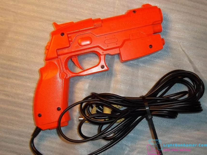
PS1 Konami Justifier
This kit installs a microswitch inside of the Playstation 1 Konami Justifier, also known as the Hyper Blaster, for improved tactility and more accurate trigger pulls.
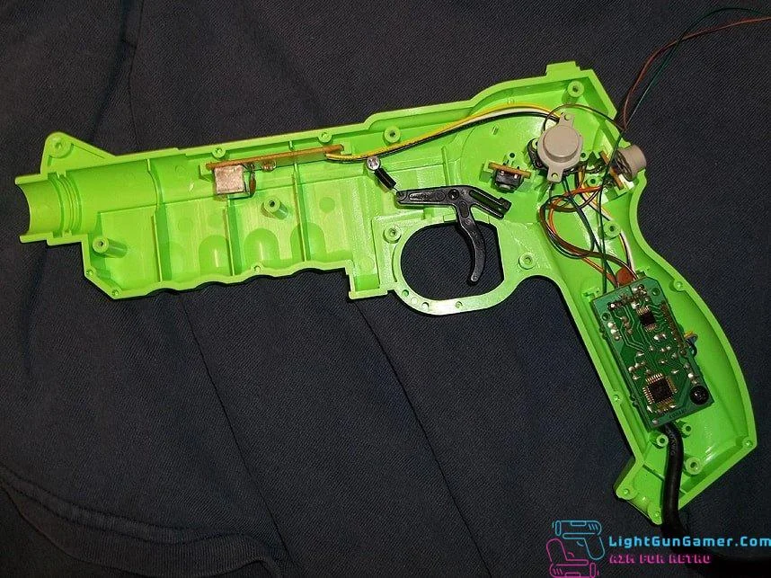
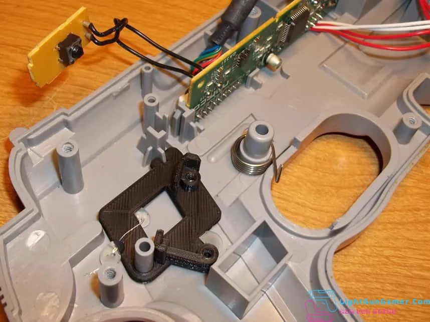
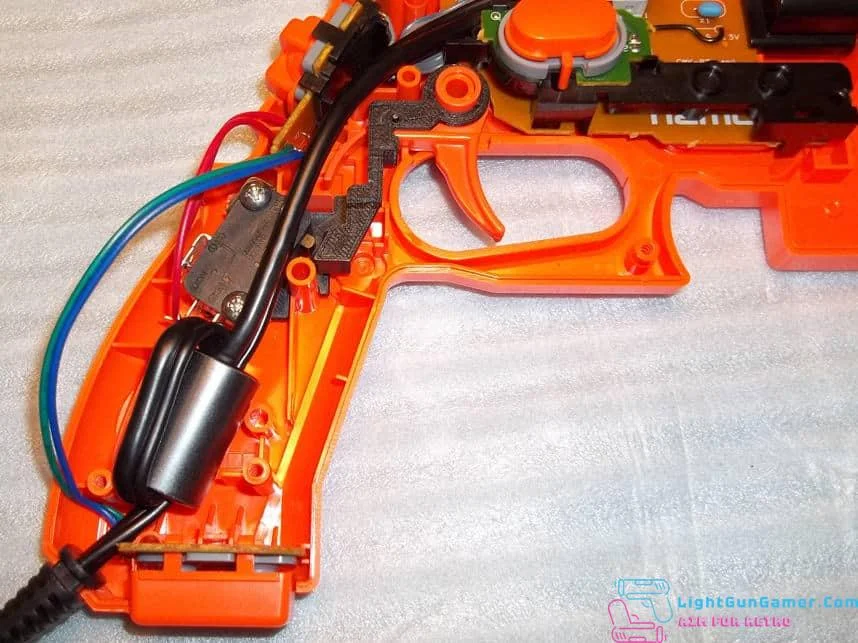
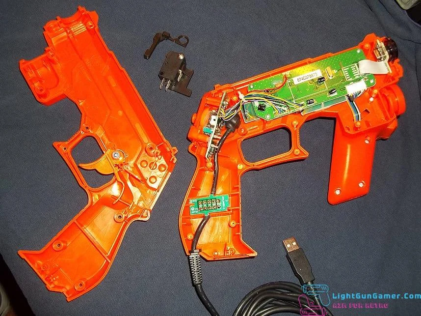
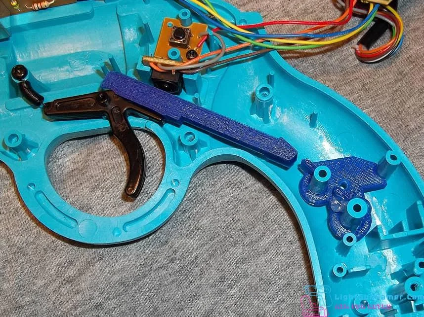
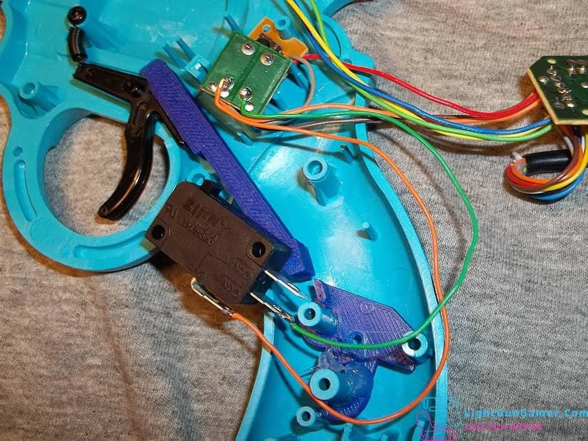
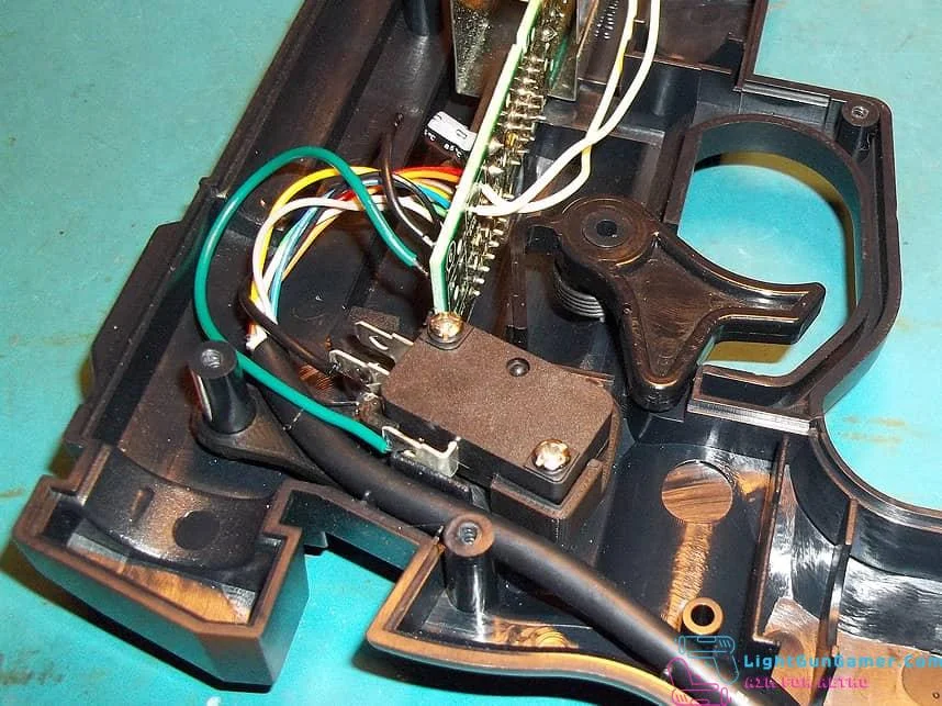
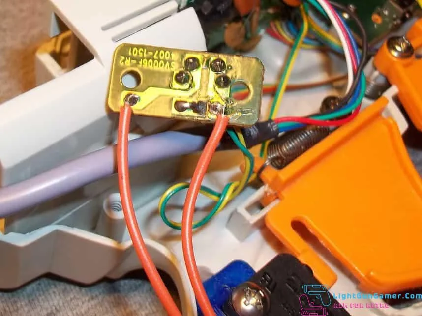
Remove all screws holding the gun shell together and lay the right half on an appropriate work surface. Note the original trigger switch board located just above the trigger piece- you’ll want to remove the board (it slides right up out of the holding tracks) and desolder the wiring from it so that you don’t hit this anymore.
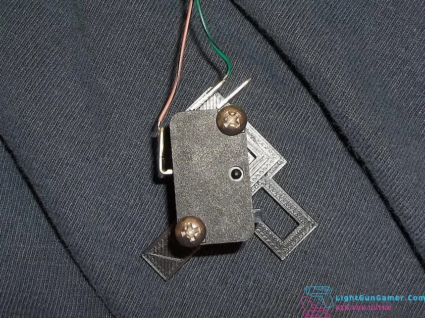
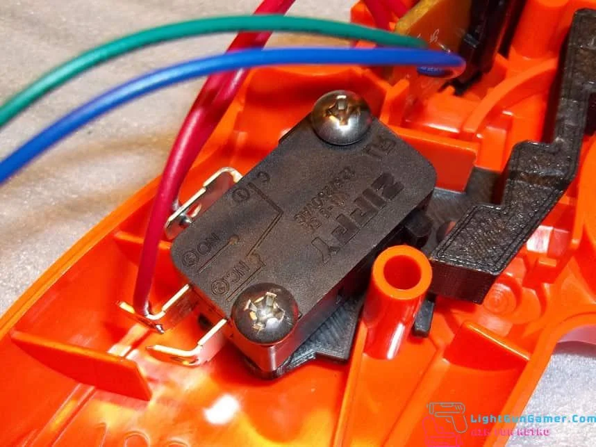
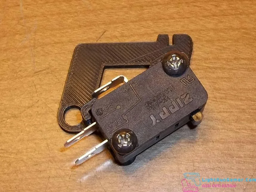
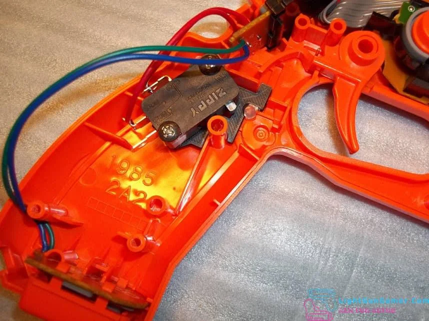
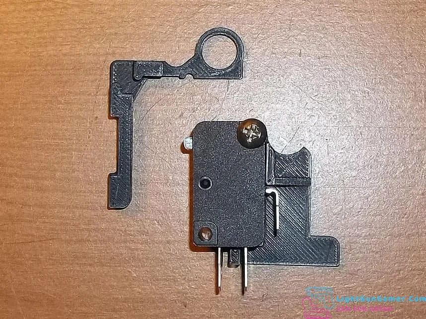
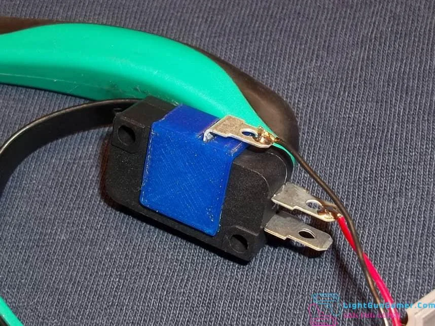
Bend the tabs on the new microswitch like so, and then solder the brown and green wire (or ground and signal) to the common and normally open tabs of the switch. You’ll want to make sure that you preserve the ground connection for the other two buttons in this gun, and you’ll probably have to add wiring of your own in order to reach the new switch location.
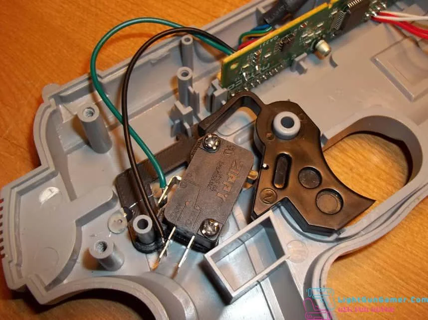
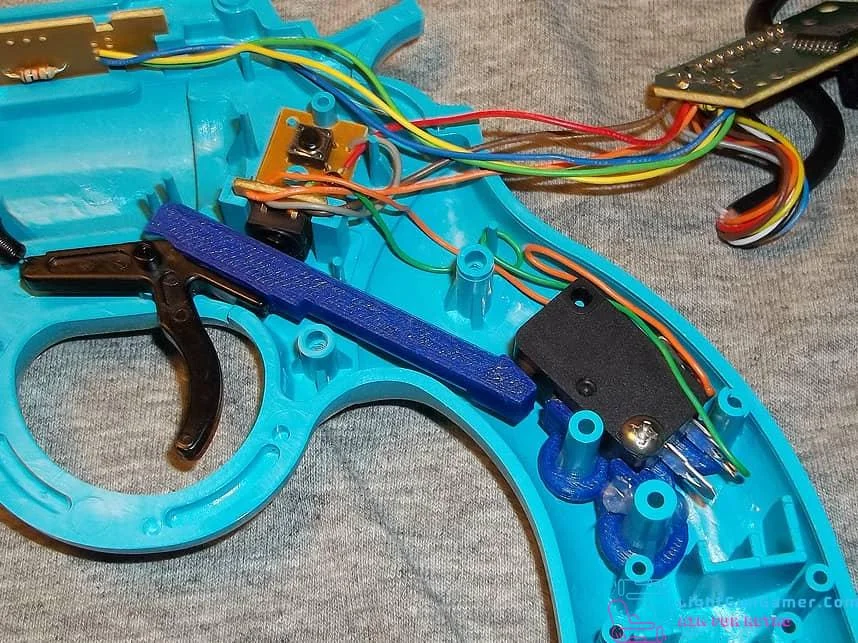
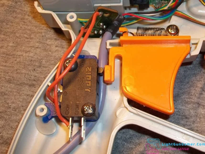
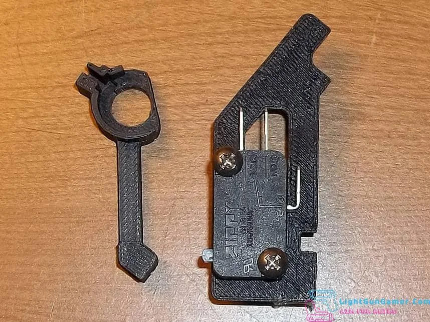
The switch bracket press fits into place as shown, and the trigger piece slips on top of the trigger to help extend its reach. You might want to secure the switch bracket with a few dots of hot glue to keep it from shifting out of alignment but this may not be necessary as it’s designed to be a snug fit.
Test the trigger to make sure that it’s actuating the microswitch, then close the gun back up- making sure that none of the wiring inside gets pinched between the plastic halves.
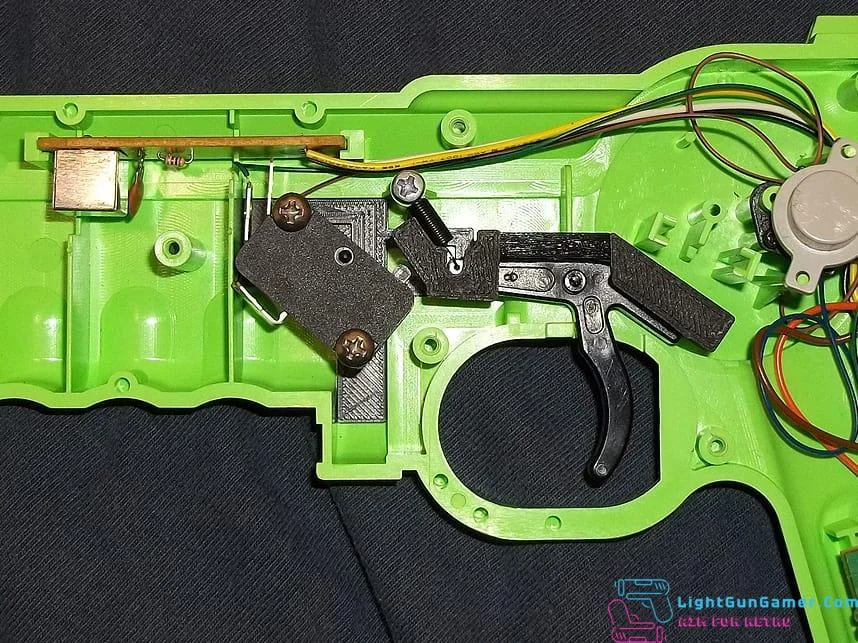
16 bit Konami Justifier
This kit installs a microswitch inside of the Konami Justifier lightgun, for improved response and a hair trigger. Though designed for the Sega Genesis model the mold is likely the same for the SNES version and should fit. Nonetheless, open yours and check just to be sure!
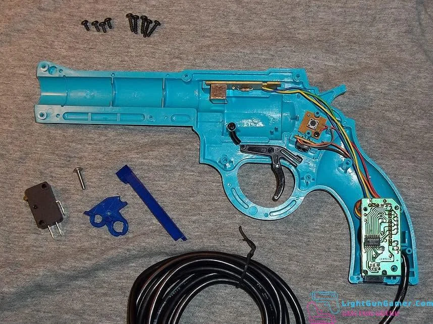
Opening the Justifier is a little trickier than most light gun housings as in addition to screws there are plastic pegs in one half snugly mating with holes in the other. After removing all of the screws you’ll probably get best results gently prying open from the barrel and sliding a plastic card along the seam, working it up as you go.
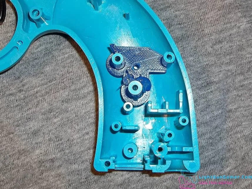
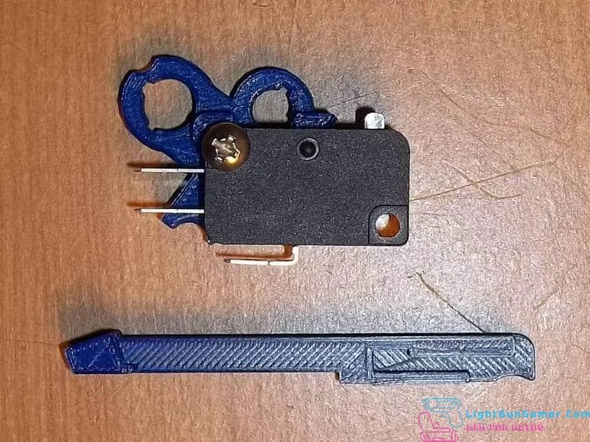
The switch bracket slips into the pegs shown above, and should be wiggle-pressed down as far as you can get it, just be careful you don’t press too hard to avoid breaking anything. A dot of hotglue will help keep it from moving out of alignment later. Basically, this bracket has to be low enough that with the switch in place, the two gun halves can come back together.
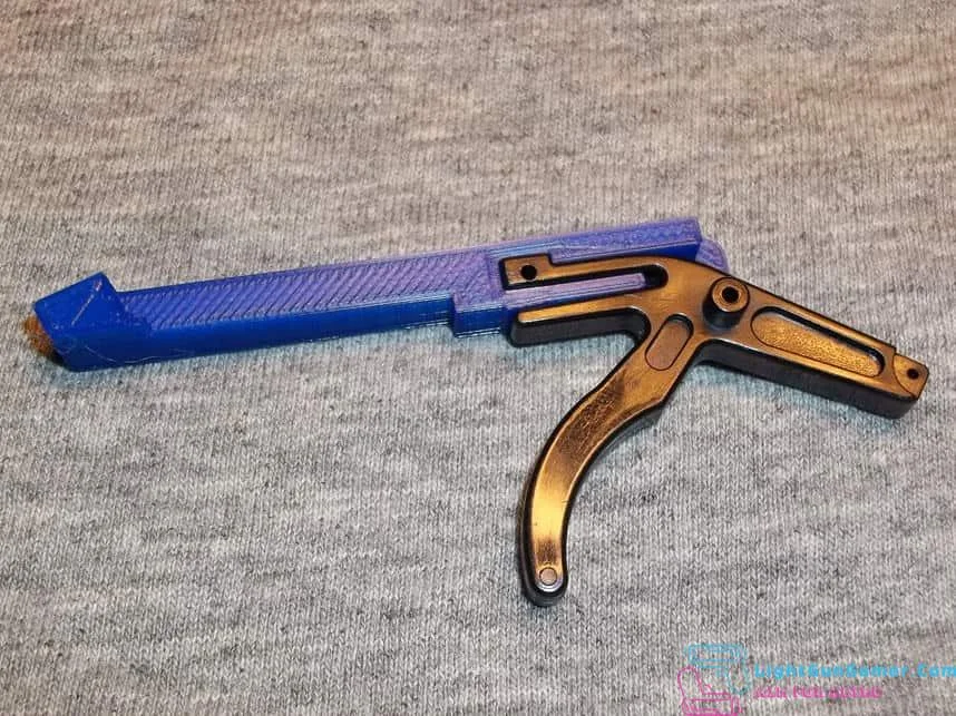
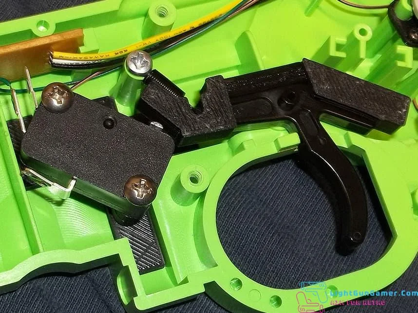
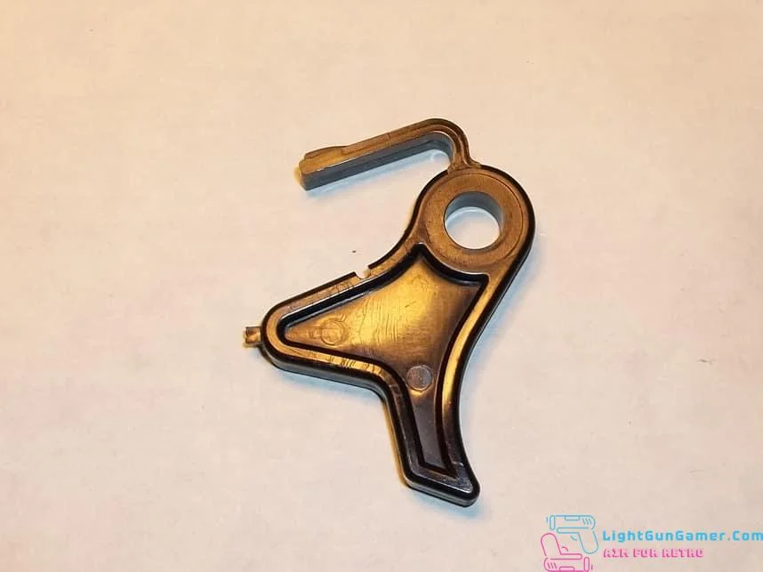
The second piece mates with the trigger as shown and is designed to be a snug fit. Still you’ll want to avoid snapping any plastic so if it’s too tight, use a small handfile where necessary. You can use a dot of hotglue afterwards if you’ve rendered it too loose.
Place the trigger into place as shown- once the microswitch is in place, it will no longer hit the original trigger button so you won’t have to remove it. I have had someone report back that their trigger extension -was- hitting the original button and had to file down plastic, so you may just want to relocate or remove this button board if necessary.
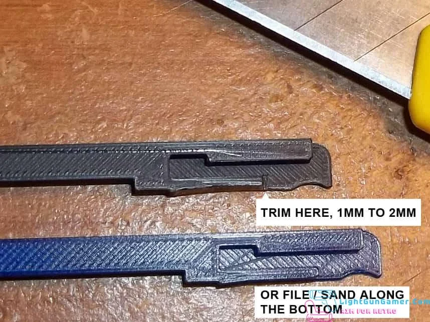
A note if you find the trigger piece is nudging into the switch too closely- you can trim away as shown above, or file/sand along the bottom edge. The idea is to keep the jaws of the trigger from spreading once the extension is added to it.
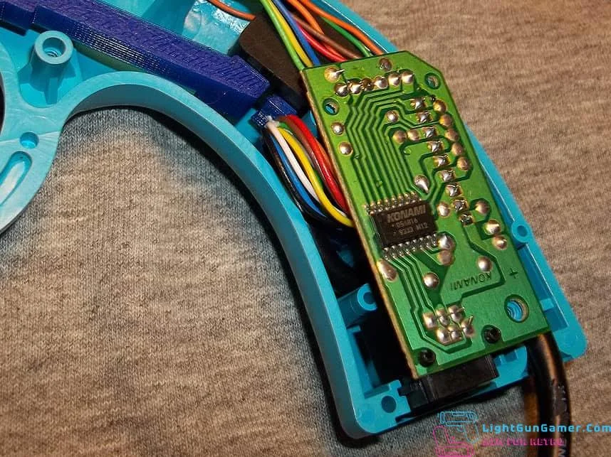
You will want to connect wires from the common and normally open tabs of the microswitch to the points shown on the original button board. It shares a ground wire with the start button so it’s easier to leave it in if you can get away with it.
Screw the switch into the bracket and route the wires so you’ll be able to close the gun up later, watching out that nothing gets pinched. Hotglue dots can help here! Be sure to test the trigger action afterwards.
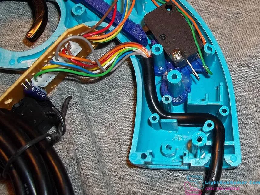
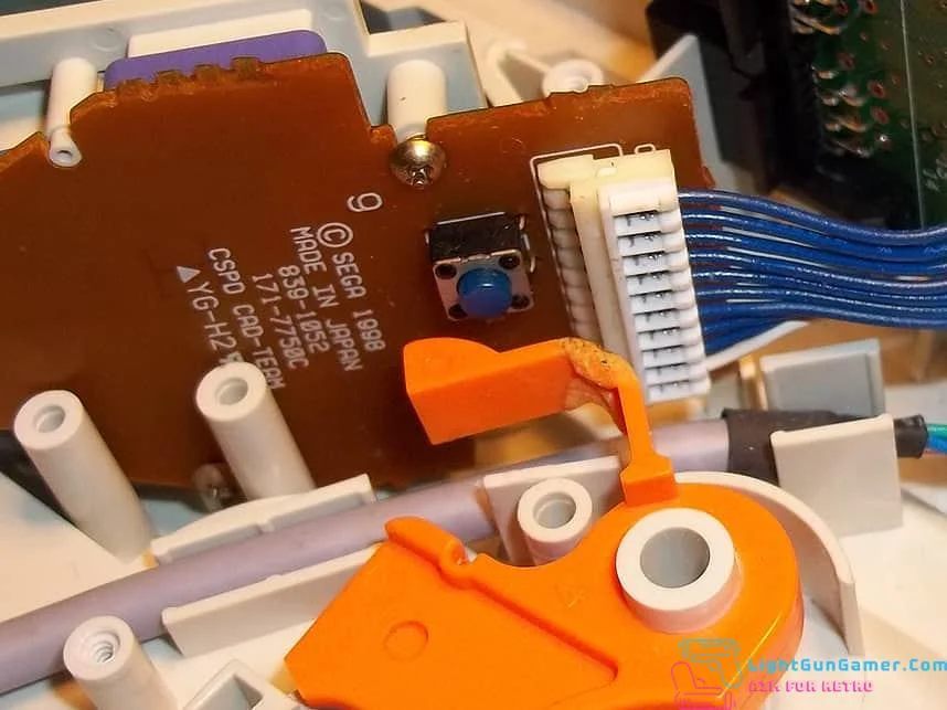
Now the main board’s controller cable should be laid into place like this,
And then the colored wiring should tuck back and under as shown. This is to prevent it from interfering with the actuation of the trigger piece. Make sure no wiring is getting pinched anywhere, especially underneath the main board. You may have to use something long and flat to keep the wiring from getting caught between the two halves as you close the gun back up.
NES Zapper
This kit removes the mechanical recoil from the Nintendo Zapper lightgun and gives the trigger a smoother, lighter touch.
This is what you should see inside the gun once you open it up, you’ll want to remove the tension springs and white plastic pieces in addition to the old switch. Be sure you don’t lose the tiny retaining rod in the trigger.
The trigger guide is designed so that you can easily press it down and then into the trigger, then return the retaining rod to hold everything together.
After you solder the new switch in, there is a spacer that I suggest you place on the underside, this helps hold the switch snugly in place and prevents rocking. Ignore the depicted wiring in the above picture! You will want to connect the wires to the normally closed and common tabs of the switch.
Everything back in place as shown above, ready to be closed up. Give the trigger a test before you do though! If you find the trigger piece has difficulty sliding along the upper track, simply take a utility knife or file and shave along the bottom edges of the 3D printed piece if you notice it’s not flush.
Sega Saturn Stunner
The Sega Stunner switch kit has been designed so that you can use standard microswitches with or without a lever.
Installation is relatively simple: temporarily remove the controller cable inside, press the bracket down into place, and maybe secure with a dot or two of hot glue to keep it from rocking out of alignment. This may not be necessary, as it is a snug fit. Remove the original button, then wire the normally open and common tabs of the switch to the original button’s location on the Stunner’s circuit board. Then reroute the controller cable back into place.
Because the back of the Stunner’s trigger has a rolled edge, it’s very important that the surface is smooth to properly actuate the new microswitch. These triggers often have a bit of plastic flashing left over from the injection molding process.
Snip the excess plastic away and sand or file the surface a bit to get it smooth.
Due to customer feedback, the kit comes with a 50 gram switch. You may want a clickier switch, or try a switch with a lever for a more rolling pull of the trigger.
If the action of the trigger feels a little coarse when it hits the switch, you still need to smooth the trigger with sandpaper or file it some more until it connects smoothly. This boils down to user preference.
Sega Dreamcast Starfire
This kit replaces the original pushbuttons of the Interact Starfire light gun with microswitches behind the triggers, for improved tactility and more accurate pulls. It is a two-piece kit for the fore and aft.
The install isn’t very complicated, just unscrew the housing and take off the right half. Be aware that the Start & B buttons on that side are tethered by wire running to the other half, so just lay it nearby and off to the side.
You’ll want to unscrew the small daughter board that holds the main trigger button, and also two of the screws on the d-pad board. Unscrew the switch from the smaller bracket of the kit as you’ll be screwing that bracket in place of the daughter board, using the original screws.
The fore trigger kit is fairly straightforward- slip it into place as shown, screw it to the d-pad board with the original screws you took out earlier, and wire it to the points above. By tapping these points, you’re reusing a diode that likely prevents ghosting. It wouldn’t hurt to secure the bracket with a few dots of hot glue so long as it doesn’t interfere with closing up the gun housing once you’re finished.
The aft trigger kit screws into place of the pushbutton board mentioned earlier. Again, securing it with hot glue helps prevent rocking.
Solder wires to the following points on the displaced daughter board- by doing this, you’re reusing a diode that prevents ghosting.
Solder the other wires to the common and normally open tabs of the switch, route the main controller cable underneath as shown, screw the switch into place on its bracket, and tuck the daughter board out of the way so nothing interferes with the trigger pull. After that, you can close the gun back up.
Sega Dreamcast HKT-7800
This kit replaces the original pushbutton of the Japan exclusive Sega Dreamcast HKT-7800 ‘Virtua’ light gun with a microswitch ahead of the trigger, for improved tactility and more accurate pulls.
First remove the original button located behind the trigger, you’ll want to take out the control board (with the d-pad and B/start buttons) and unscrew the PCB to desolder or clip it out.
Solder two wires to the two points as shown.
This installation can be a little tricky, the trigger piece mates with the other half of the gun shell while still attached to the trigger itself. You may have to open the gun again and make some adjustments with a hand file so the trigger doesn’t feel sticky.
After placing the switch bracket, you can thread the new wiring through the middle before connecting to the normally-open and common tabs of the switch. This helps keep the wires from snagging on the trigger piece.
As mentioned earlier, the trigger piece sort of mates with the opposite half of the shell- you’ll probably want to do a test fitting here as shown, just to make sure it swings easily. If it doesn’t, use a round handfile to sand the inside of the hole evenly to make it loose, but don’t take too much out.
Fitting of the trigger piece sits as shown.
Opposite side.
Finally, set the trigger into place and then close the gun back up, making sure that the hollow peg of the opposite gun shell seats into the large hole of the 3D printed piece. Test the trigger action a few times before screwing it shut, and you may also want to place a few dots of hot glue as shown on the switch bracket to keep it from swinging out of alignment.